|
This page covers what you need to know
to modify your Loreo (or Argus) Stereo Camera for improved
performance.
Why Modify My Camera?
There are a number of reflective
surfaces in the Loreo Stereo Camera that serve no function
in the imaging process. These surfaces were left mirrored
either for convenience or for general aesthetics.
Unfortunately, they have a tendency to divert stray light
into the lenses in a relatively unpredictable manner. The
result is pictures with streaks and lens flare.
The solution is to make the
unnecessarily-mirrored surfaces non-reflective. With a
paint brush, a screw driver, some flat black enamel, and
the instructions below, you should be able to modify your
Loreo camera to improve the quality of your stereo
photos.
Disclaimer
Neither the author nor Evermore
Enterprises is affiliated with Loreo Asia Limited (the
maker of the Loreo Stereo Camera) except as a user of the
camera. Loreo Asia Limited has not sanctioned these
modifications to their cameras and such modifications may
void any warranty rights accorded owners of Loreo Stereo
Cameras. The author takes no responsibility for the outcome
of performing the procedure below.
[This hack worked for me. Your mileage may vary.]
What do I need for this Project?
-
A small Phillips
screwdriver, of the sort used for some
electronics work and watch repair.
-
A paint brush - A
small, flat brush is optimal. Try an artist's brush
size of 1.
-
Flat black enamel
paint - Testor model enamel seems to work
well. The important thing is to get a flat black paint
that will stick to a smooth plastic surface. Be sure to
stir the paint thoroughly before use.
- Tweezers
(optional) - Tweezers may be useful in extracting and
repositioning the small screws during disassembly and
re-assembly.
What do I do?
Disassemble the Camera:
-
Remove the batteries and any film
from the camera.
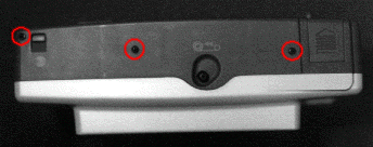
Figure 1
-
Remove the three small screws on the
bottom surface of the camera (circled in figure
1, above.) Keep track of the screws and which
screw belongs in which hole. The screws are of
different lengths.
-
Carefully remove the bottom panel
from the camera.
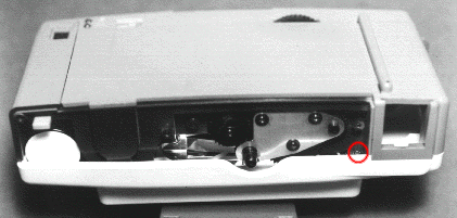
Figure 2
-
Remove the first screw retaining the
front panel of the camera. It is located at the bottom
of the camera on the right-hand side, just under the
bottom panel (circled in figure 2,
above.) You will have to angle the screwdriver slightly
to turn this screw as the back panel prevents direct
access. Use caution not to strip the head of the
screw.
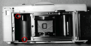
Figure 3
-
Open the back of the camera and
remove the other two screws retaining the front panel.
These screws are located at the top and bottom of the
film cartridge chamber (circled in figure
3, above.) After removing the screws, close
the back panel to help keep debris out of the film
chamber and shutter assembly.
-
Open the flash hood and
loosen (do not remove) the screw immediately
under it. The screw is in the center of the camera.
Do not remove the top panel. It is
unnecessary and will complicate re-assembly.
- It should now be possible to
remove the front panel of the camera. It may necessary to
jiggle the front panel as you pull. There are two tabs on
the front panel that tuck under the top panel of the
camera. Use caution not to break them.
Paint the Extra Mirrored Surfaces:
The two
vertical mirrored surfaces on the left and right side of
the camera are the imaging mirrors. As they are made from
polished plastic, they will scratch very easily.
Do not touch these mirrors with anything.
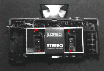
Figure 4
-
The main unnecessarily-mirrored
surfaces are on the inside top and bottom of the
imaging assembly (marked with Xs in figure
4, above.) Paint these surfaces with the
enamel. Use the paint conservatively and, as you paint
each surface, hold the camera so that any excess paint
will not run onto the imaging mirrors. If you
contaminate the imaging mirrors with a small amount of
paint, it is best to leave the paint in place. The
imaging mirrors will be scratched by even the finest
optical clothes and the gentlest attempts to remove
it.
-
Paint the outer rim of the imaging
assembly. Again, use caution to avoid contaminating the
imaging mirrors with paint.
-
Carefully pry off the metal plate
that rests across the center of the imaging
assembly.
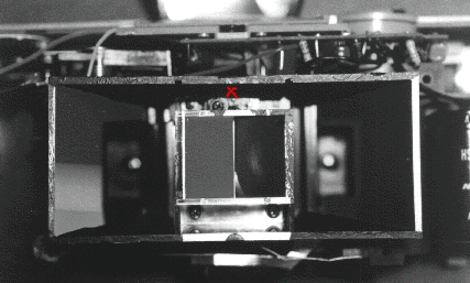
Figure 5
-
Paint the reflective inner top
surface of the imaging assembly (marked with an X in
figure 5, above.)
- Cover or tilt the camera to
protect the imaging mirrors from dust and allow the paint
to dry completely.
Reassemble the Camera:
Reassembling the camera is the reverse
of the disassembly procedure above.
-
Replace the metal nameplate that
rests across the center of the imaging assembly.
-
Replace the front panel, carefully
tucking the tabs under the top panel. Be extra careful
to make certain the shutter release assembly is
positioned correctly. If it is not, the light meter may
work improperly after you reassemble the camera. If
this happens, the contact may become sufficiently bent
that it is necessary for you to construct a cardboard
or plastic shim to correct it.
-
Tighten the screw on the top panel,
underneath the flash hood.
-
Open the back of the camera. Replace
and tighten the two screws inside the film chamber
(circled in figure 3, above.) Close
the back of the camera.
-
Replace and tighten the screw just
under the bottom panel on the right side of the camera
(circled in figure 2,
above.)
- Replace the bottom panel of the
camera, replacing and tightening the three screws that
hold it in place (circled in figure 1,
above.)
Completion:
You have now completed the modification
to your Loreo Stereo Camera. You should see a big
improvement in the quality of your Loreo stereo photos.
Other Suggestions:
The weak flash of the Loreo camera can
be improved somewhat by mirroring the top of the camera
underneath the flash hood. The easiest way to do this is to
cover it with a piece of aluminum foil. Smooth any wrinkles
from the foil. Cut and pre-fit the foil using a scalpel or
small hobby knife (e.g. an X-Acto (TM) knife.) Glue the
dull side of the foil to the top of the camera.
You can also obtain a slave flash unit that
will be triggered by the built-in flash on your Loreo.
Check with your local camera retailer for more
information.
Comments and Questions:
Please direct any comments or questions
about this document or the Loreo Stereo Camera
modifications to the author at contact@evermore.com.
Copyright 1995, Evermore Enterprises - Please do not mirror or distribute without this notice.
Last Modified: Thursday, October 29, 1998
|


